
The Loose Terminal a Breaker Cannot See
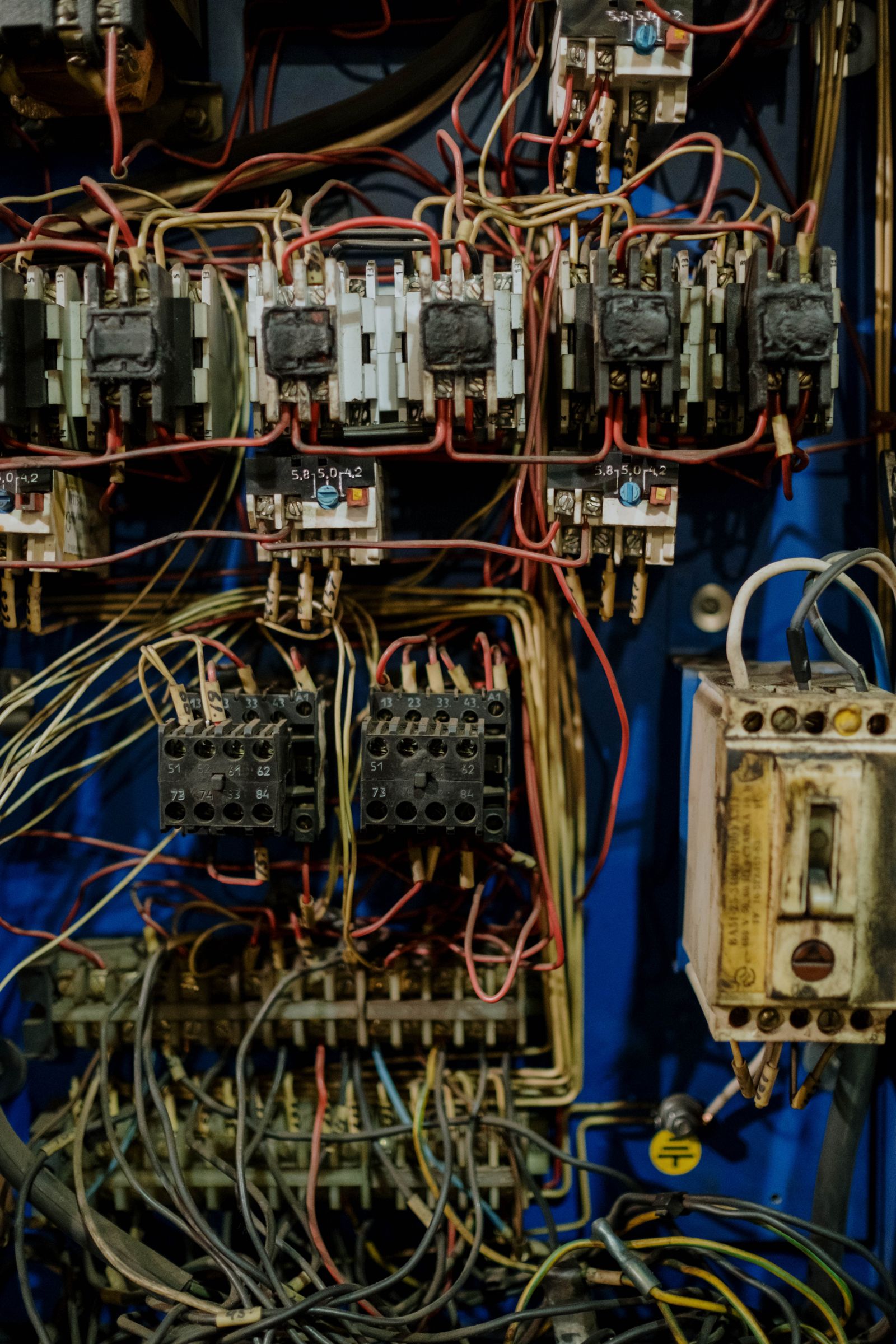
A loose joint changes resistance, not current — so overcurrent protection is blind by construction. MAIB 24/2011: 25 A through a 32 A breaker, and a fire.
A circuit breaker measures current. A loose termination changes resistance. Those are different quantities, and at a series high-resistance joint the current barely moves — so overcurrent protection is not failing to detect the fault, it is incapable of detecting it. On Commodore Clipper the fault current stayed at the reefer's normal 25 A load behind a 32 A breaker, and the terminal reached its own melting point.
This matters on a vehicle deck because reefer sockets are the densest population of high-current connections on the ship, made and broken every voyage, often by people who are not electricians. The space detector sees the fire. The breaker sees neither the fault nor the fire. Everything useful happens in between, and it is a measurable band.
Why the breaker is blind by construction
Because the fault adds milliohms to a circuit whose load impedance is orders of magnitude larger. Power dissipated at the joint is P = I²R, and R at a degraded termination might rise from single-figure microhms to tens of milliohms — enough to dissipate watts in a contact the size of a fingernail, and nowhere near enough to change the current the breaker is watching. A thermal-magnetic breaker responds to overcurrent; a residual-current device responds to an imbalance between line and neutral. A series high-resistance joint produces neither signature. It is a heat source inside a healthy-looking circuit.
MAIB 24/2011 quantifies it. The supply breaker feeding the socket was an ABB System pro M rated 32 A with a K-characteristic, chosen for motor starting loads. Tested afterwards by an electrical contractor it tripped at 84 A, then at 77 A, then at 70 A on successive tests — the progressive reduction being heat accumulating in the thermal element. Correct behaviour, well inside specification, and never within reach of a fault limited to the ~25 A the trailer's refrigeration unit was drawing. The report's first conclusion states it plainly: the protection devices 'met the classification society's requirements and were functioning correctly. However, they were not capable of detecting the fault in the reefer cable.'
What the temperature tells you, and the I² trap
Thermography finds these joints, but surface temperature alone is an unreliable measure of severity. The NETA severity convention reads a temperature rise against a reference — a similar component under the same load, or ambient — with roughly 1–3°C indicating a possible deficiency warranting investigation and 4–15°C a probable deficiency to repair as time permits. Those bands are useful only if the circuit is loaded when you look.
That is the trap. Fault power rises as the square of the current, so the same defect that shows a barely-visible rise at part load produces four times the heat at double the current. A survey walked during loading, with the reefer units off or idling, will under-read every connection on the deck — and a car deck is precisely where load is intermittent by design. Any thermal criterion applied to reefer sockets has to specify the load condition it was measured at, or it means nothing.
The melting-voltage check turns a small ΔT into a real number
There is a better test than 'how warm is it', and it converts a modest temperature rise into the quantity that actually predicts failure. A worked example from the infrared-thermography literature: a connection running 30°C, only 7°C above its neighbours, at 6 A on a circuit rated 200 A. Estimate the heat conservatively at 1 W. Then R = P/I² = 1/36 ≈ 0.028 Ω — 28 milliohms, against a typical healthy value below 10 microohms. The voltage drop across the joint is ΔV = I·R = 0.17 V, about 40% of copper's 0.43 V melting voltage; and the current at which that melting voltage is reached is ΔV/R = 0.43/0.028 ≈ 15 A.
Read that back in operational terms. A joint dismissed as 'seven degrees warm' is already running at thousands of times its intended resistance, and needs only 15 A on a 200 A circuit to reach the voltage at which copper melts. Now apply the same arithmetic to a reefer socket that sits at 25 A every time a trailer is plugged in. The Clipper terminal was reported by its manufacturer as melting between 900 and 925°C, and it melted.
What actually detects a high-resistance joint
- Arc fault detection. IEC 62606 devices are built for exactly this failure class — arcing from glowing contacts, loose terminals and poor connections that does not draw enough current to trip a conventional breaker. The standard's scope is household and similar a.c. circuits, which is the gap: there is no equivalent requirement for a ship's reefer supply.
- Continuous temperature at the connection, not in the space. A deck smoke detector is metres away and answers a later question. A thermal channel on the socket answers this one, and it is the only method that works while the deck is closed and loaded at sea.
- Thermography under load, with the load recorded. Periodic IR is effective if the survey is scheduled when reefers are running and the report states the current at which each ΔT was measured.
- Resistance or voltage-drop measurement at the joint during maintenance — the direct measurement, and the one the melting-voltage method approximates from a distance.
- Design and assembly controls: the correct IP rating (Clipper's sockets were IP44 where class required IP55), termination type, torque discipline, and quality control over cable assemblies — the Clipper's reefer cables had been made up on board since 2006, and the failure was an assembly error in an insulation-displacement terminal.
What this means for a vehicle deck
Treat reefer sockets as a monitored population, not as fittings. They are high-current connections in a salt-laden, vibrating, mechanically abused space, connected and disconnected by longshoremen on a schedule that leaves no time for inspection, and they sit inside the enclosed volume where a fire is hardest to reach. Every protective device upstream of them is looking at current, and the failure mode that has actually burned a ro-pax does not move current.
The practical specification follows from that: connection-level thermal monitoring on the socket population, thermographic survey scheduled under load with the load documented, IP55 as the class requirement actually demands, and an assembly-quality record for any cable made up on board. None of it is exotic, and all of it addresses a gap that overcurrent protection cannot be asked to close — because the fault, by its nature, never reaches the breaker's threshold.
How RoRoSAFE helps
A high-resistance joint is found by its heat, not by the breaker. RoRoSAFE's per-vehicle thermal sensing reads local temperature at each parked vehicle against its own baseline and its neighbours, the same comparison this article recommends. An abnormal rise at a vehicle, whatever its electrical cause, is flagged before visible smoke.
Pilot: one deck · installed alongside the berth · no drydock · 6 months of dashboard access
Sources
- 1. MAIB Report No 24/2011, 'Report on the investigation of the fire on the main vehicle deck of Commodore Clipper while on passage to Portsmouth, 16 June 2010' (November 2011), read in full: §1.12.3 electrical examination — ABB 'System pro M' 32 A K-characteristic breaker tripping at 84 A, 77 A then 70 A on successive tests with the reduction attributed to heat build-up in the thermal tripping mechanism; brown-phase termination loose inside a Mennekes 'StarTop' IP44 plug with insulation-displacement terminals, raising resistance and producing heating and arcing; terminal material melting point reported by the manufacturer as 900–925°C; fault current limited to the ~25 A load so the supply breaker would not trip; class requirement for IP55 sockets overlooked with IP44 fitted; reefer cables made up on board by ship's staff from 1 May 2006. §3.1 conclusion 1 for the quoted finding on protection devices.
- 2. IEC 62606, 'General requirements for arc fault detection devices (AFDDs)' (2013, with amendments 2017 and 2022): devices performing detection and discrimination of arcing current with regard to fire hazards, addressing arc faults from insulation breakdown and poor connections that may not produce sufficient overcurrent to operate a conventional protective device. Scope is household and similar a.c. circuits.
- 3. G. B. McIntosh (Snell Infrared), 'Condition Assessment of Electrical Connections Utilizing Infrared Thermography', QIRT 2014 — the worked melting-voltage example quoted here (30°C fault, 7°C rise, 6 A on a 200 A circuit, ≥1 W dissipation, R = P/I² ≈ 28 mΩ against a typical value below 10 µΩ, ΔV = 0.17 V against copper's 0.43 V melting voltage, melting voltage reached at ≈15 A), and the point that fault power increases as the square of the current so surface temperature alone is an unreliable severity indicator. References NFPA 70B for surveying energised and under load.
- 4. InterNational Electrical Testing Association (NETA) severity convention for ΔT between similar components under the same load: 1–3°C a possible deficiency warranting investigation; 4–15°C a probable deficiency to repair as time permits.
- 5. Companion RoRoSAFE analyses — 'Commodore Clipper: The Alarm Reset 7 Times' (the casualty in full, including the seventeen minutes after this fault ignited), 'Marine-Grade Cable Design for Decks', 'Salt Mist, IP66, and the Coating Spec' and 'What a False Alarm Costs a Master at Sea'.
Questions, answered
Why does a circuit breaker not trip on a loose connection?+
Because a loose joint changes resistance, not current. It adds milliohms to a circuit whose load impedance is far larger, so the current the breaker monitors is essentially unchanged while watts are dissipated at the contact. A thermal-magnetic breaker responds to overcurrent and an RCD to earth imbalance; a series high-resistance joint produces neither signature.
How hot does a connection have to get before it is dangerous?+
Surface temperature is the wrong question. NETA treats a 1–3°C rise over a comparable component as a possible deficiency and 4–15°C as a probable one, but fault power rises with the square of the current — so the same defect looks mild at part load and severe at full load. Severity depends on the joint's resistance and the current it will carry, not the temperature you happened to measure.
What is the melting-voltage method?+
A way of converting a small temperature rise into a failure prediction. Estimate the heat dissipated at the joint, derive resistance from R = P/I², then compute the voltage drop ΔV = I·R and compare it with the metal's melting voltage — about 0.43 V for copper. In one published example a joint only 7°C warm proved to be at 28 milliohms and 40% of melting voltage.
What detects this fault on a ship's reefer sockets?+
Not the breaker. Arc fault detection to IEC 62606 targets exactly this failure class but is scoped to household circuits, with no marine equivalent required. Practical options are continuous temperature monitoring at the connection itself, thermographic survey scheduled while the reefers are running with the load recorded, and resistance or voltage-drop measurement during maintenance.
Continue the thread

Commodore Clipper: The Alarm Reset 7 Times
A reefer plug ignited on a Condor ro-pax in 2010. Detection worked — 16 sensors, 81 alarms. The crew read a fault, silenced it, and lost 17 minutes.

Marine-Grade Cable Design for Decks
Twenty meters of cable damaged by a tire is not a sensor problem — it is a cable problem. Here is what we learned about specifying for the environment.

Salt Mist, IP66, and the Coating Spec
The first conformal coat passed lab spray tests and failed in service. The second passed in service and failed thermal cycling. The third one stuck.

Redundant Power for the Segment Master
A segment master that loses power loses a whole deck. The redundancy story has to start at the supply rail, not at the network port.

What a False Alarm Costs a Master at Sea
Seventeen minutes, in the one case with timestamps. On Commodore Clipper a real fire read as a detector fault: 11 silences, 7 resets, then the system died.

How Are Thermal Hotspots Detected?
Measuring temperature on a cargo deck is easy; deciding which rise is real is not. Relative thresholds and neighbour checks separate faults from noise.

Marine-Spec Thermal Cameras on Deck
The spec that decides fitment is not resolution. It is which EN 54 part the camera certifies to, because that fixes which FSS Code duty it can meet.
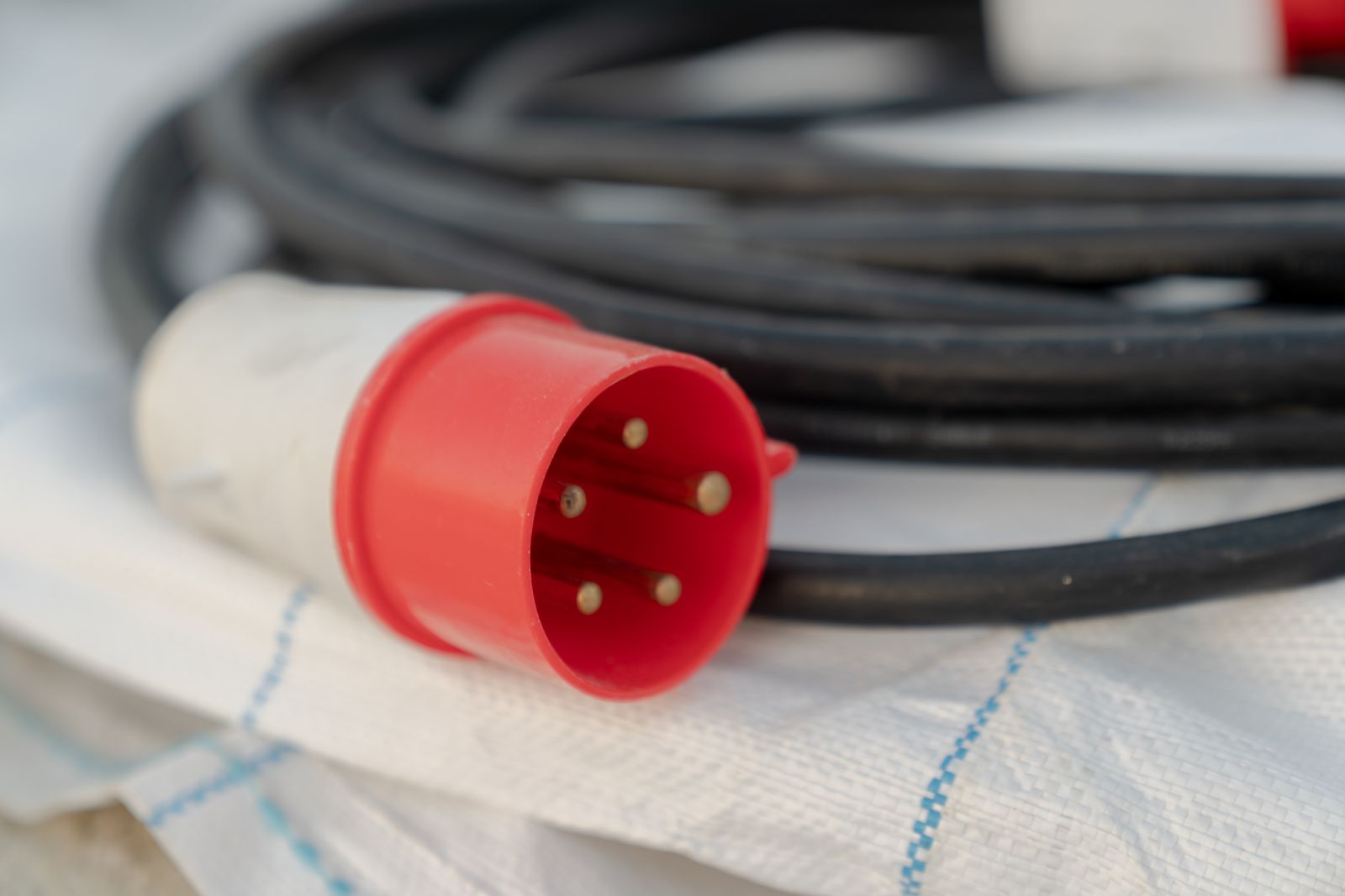
Are Reefer Trailers a Ferry's Hidden Fire Risk?
Yes. EMSA found reefer units the most fire-prone ro-pax cargo, and the weak point is often the plug and cable linking the trailer to the ship's power.